
Boiler design
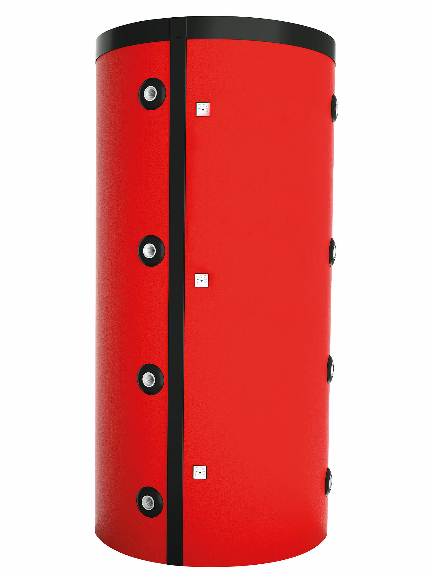
Fleece insulation X
Up to 38 per cent less storage loss as compared to soft foam insulation thanks to the energy-saving and environmentally friendly 100 mm fleece insulation.
Indicating thermometer X
3 display thermometers allow easy reading of the accumulator tank temperatures at the top, middle and bottom.
6/4” Connection X
Very little space required and suitable for niches due to the connections arranged at the front.
Hooked strip X
Simple and quick installation and also sleek visual appearance due to the simultaneous function of a cable duct.
Raised or deep-drawn connection pipes X
Best energy utilisation by extracting the heating water at the highest temperature level (top) and also loading the lower range that is not normally used.
Cogent to the smallest detail
- Up to 38 per cent less storage loss as compared to soft foam insulation thanks to the energy-saving and environmentally friendly 100 mm fleece insulation.
- 3 display thermometers allow easy reading of the accumulator tank temperatures at the top, middle and bottom.
- Very little space required and suitable for niches due to the connections arranged at the front.
- Simple and quick installation and also sleek visual appearance due to the simultaneous function of a cable duct.
- Best energy utilisation by extracting the heating water at the highest temperature level (top) and also loading the lower range that is not normally used.
The advantages at a glance
+ Heat loading without auxiliary energy due to patented cascade solution
+ Optimum use of heat thanks to raised connection pipes
+ High-quality, environmentally friendly 100 mm ECO SKIN fleece insulation

AccuWIN - heat accumulator
Thanks to the upper connection pipe, water is only taken from the highest temperature level and sent to the heating system. The lower pipe only carries water from the coldest temperature zone to the heating boiler. This allows full use to be made of the entire accumulator volume.

Loading the heat storage cascade
1/ Loading cascade accumulator
The first cascade accumulator is loaded using the accumulator load control system and hydraulic arrangement. Since only a little water needs to be heated, the energy can be extracted quickly. This also helps to reduce radiation losses.

2/ Loading second accumulator
If the temperature near the middle connection line reaches 45 °C, a valve opens and the second accumulator is loaded without auxiliary energy thanks to the thermal lift. At the same time, the bottom part of the first accumulator remains free, for example for energy from the solar heating system.

3/ Both accumulators have been heated through
Once sufficient energy is supplied, both accumulators are completely heated through.

Discharging the heat storage cascade
1/ Unloading first accumulator
When heat is needed, it is discharged from the first accumulator tank. This means that space is made available again in the lower area for the addition of new solar energy. The temperature is ideally stratified in both accumulators because the bottom connection is used for the return. So the second heat accumulator remains warm in the upper part.

2/ Unloading second accumulator
If the temperature in the first heat accumulator falls below that in the second, the heat is moved from the second to the first accumulator using a pump. The ideal heat stratification is therefore retained and all the stored energy can be used.

Technical data
The AccuWIN is available in a total of three different forms.
| Type | AccuWIN 825 | AccuWIN 1000 | AccuWIN 1500 | |
| Nominal content | l | 825 | 1,000 | 1,500 |
| Diameter with/without insulation | mm | 990/790 | 990/790 | 1,200/1000 |
| Height with/without insulation | mm | 1,940/1860 | 2,135/2050 | 2,235/2150 |
| Overall height without insulation | mm | 1,905 | 2,090 | 2,270 |
| Minimum room height | mm | 1,960 | 2,190 | 2,290 |
| Weight with/without insulation | kg | 120/110 | 140/130 | 220/205 |
| Supply and return connections | Int. thr./Ext. thr. | 6/4" int. thr. | 6/4" int. thr. | 6/4" int. thr. |
| Connection ports | Int. thr./Ext. thr. | 6/4" int. thr. | 6/4" int. thr. | 6/4" int. thr. |
| Max. permissible operating pressure of heating system | bar | 3 | 3 | 3 |